Kappa
“Great things are not done by impulse, but by a series of small things brought together.”
Hack The Box
Networking Primer - Layers 1-4
This section serves as a quick refresher on networking and how some standard protocols we can see while performing traffic captures work. These concepts are at the core of capturing and dissecting traffic. Without a fundamental understanding of typical network flow and what ports and protocols are used, we cannot accurately analyze any traffic we capture. If this is the first time you encounter some of these terms or concepts, we suggest completing the Introduction to Networking Module first.
Networking Models
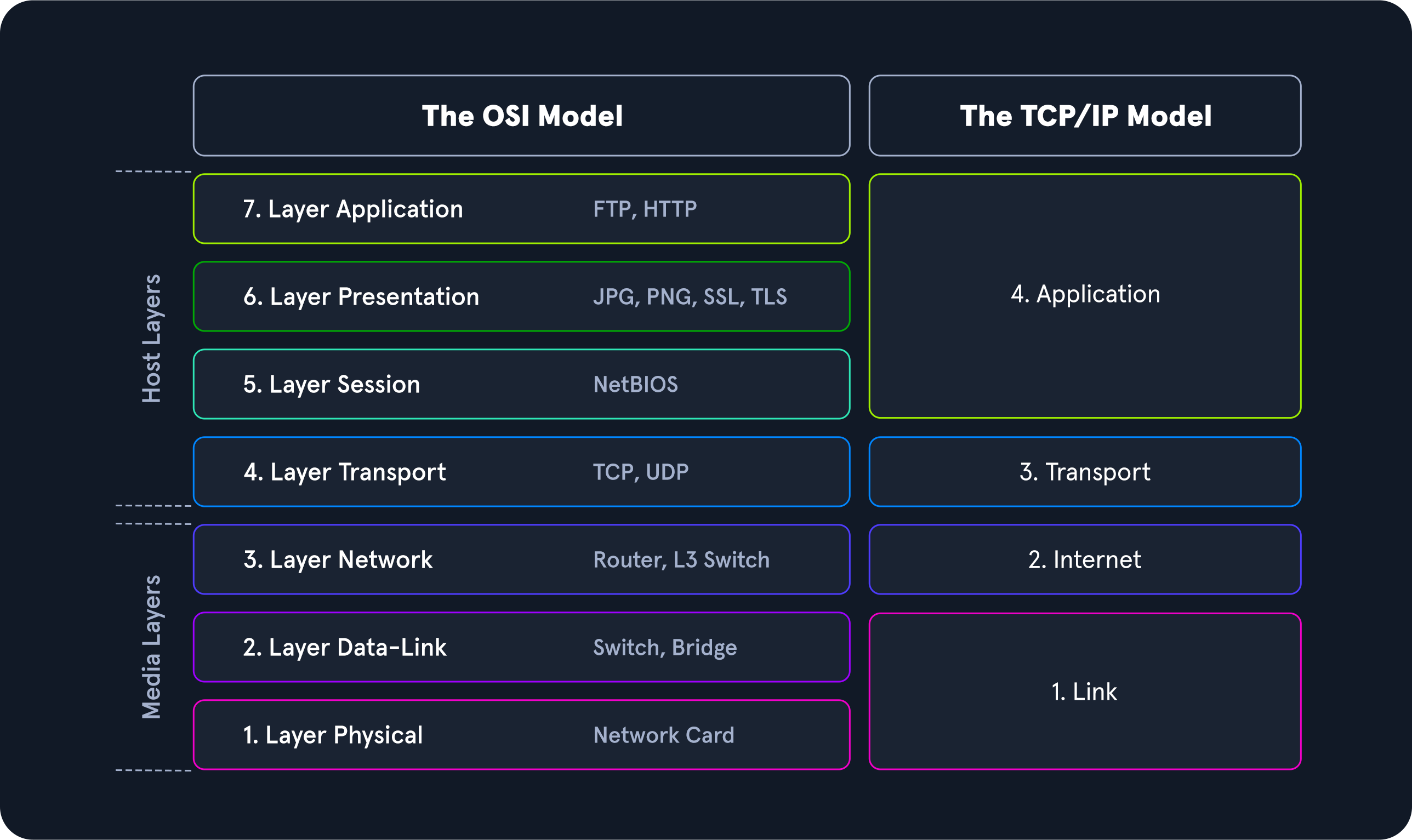
The image above gives a great view of the Open Systems Interconnect (OSI) model and the Transmission Control Protocol - Internet Protocol (TCP-IP) model side by side. The models are a graphical representation of how communication is handled between networked computers. Let's take a second to compare the two:
          Trait         OSI       TCP-IP
          Layers        Seven     Four
          Flexibility   Strict    Loose
          Dependency    Protocol independent & generic  Based on common communication protocols
When examining these two models, we can notice that the OSI model is segmented more than the TCP-IP model. This is because it is broken down into small functional chunks. Layers one through four of the OSI model are focused on controlling the transportation of data between hosts. This control includes everything from the physical medium used for transmission to the protocol utilized to manage the conversation or lack thereof when transporting data. Layers five through seven handle the interpretation, management, and presentation of the encapsulated data presented to the end-user. Think of the OSI model as the theory behind how everything works, whereas the TCP-IP model is more closely aligned with the actual functionality of networking. The TCP-IP model is a bit more blended, and the rules are flexible. The TCP-IP model comprises four layers where layers five, six, and seven of the OSI model align with layer four of the TCP-IP model. Layer three deals with transportation, layer two is the internet layer which aligns with the network layer in OSI, and layer one is the link-layer which covers layers two and one of the OSI model.
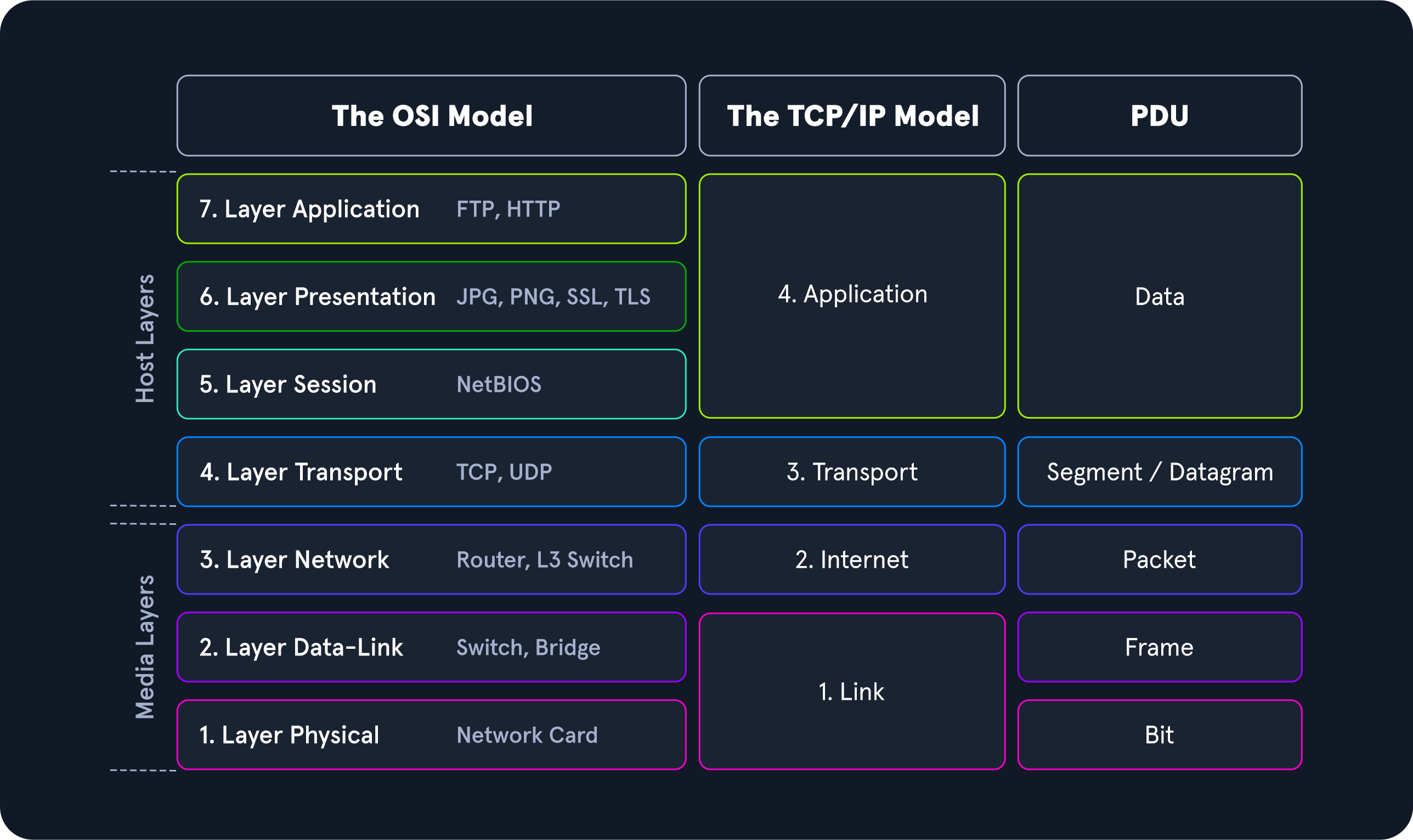
Throughout this module, we will examine many different Protocol Data Units (PDU), so a functional understanding of how it appears in theory and on the wire is required. A PDU is a data packet made up of control information and data encapsulated from each layer of the OSI model. The breakout below will show how the layers in the two models match up to a PDU.
PDU Example
When inspecting a PDU, we need to keep the idea of encapsulation in mind. As our data moves down the protocol stack, each layer will wrap the previous layers' data in a new bubble we call encapsulation. This bubble adds the necessary information of that layer into the header of the PDU. This information can vary by level, but it includes what is held by the previous layer, operational flags, any options required to negotiate communications, the source and destination IP addresses, ports, transport, and application layer protocols.
PDU Packet Breakdown
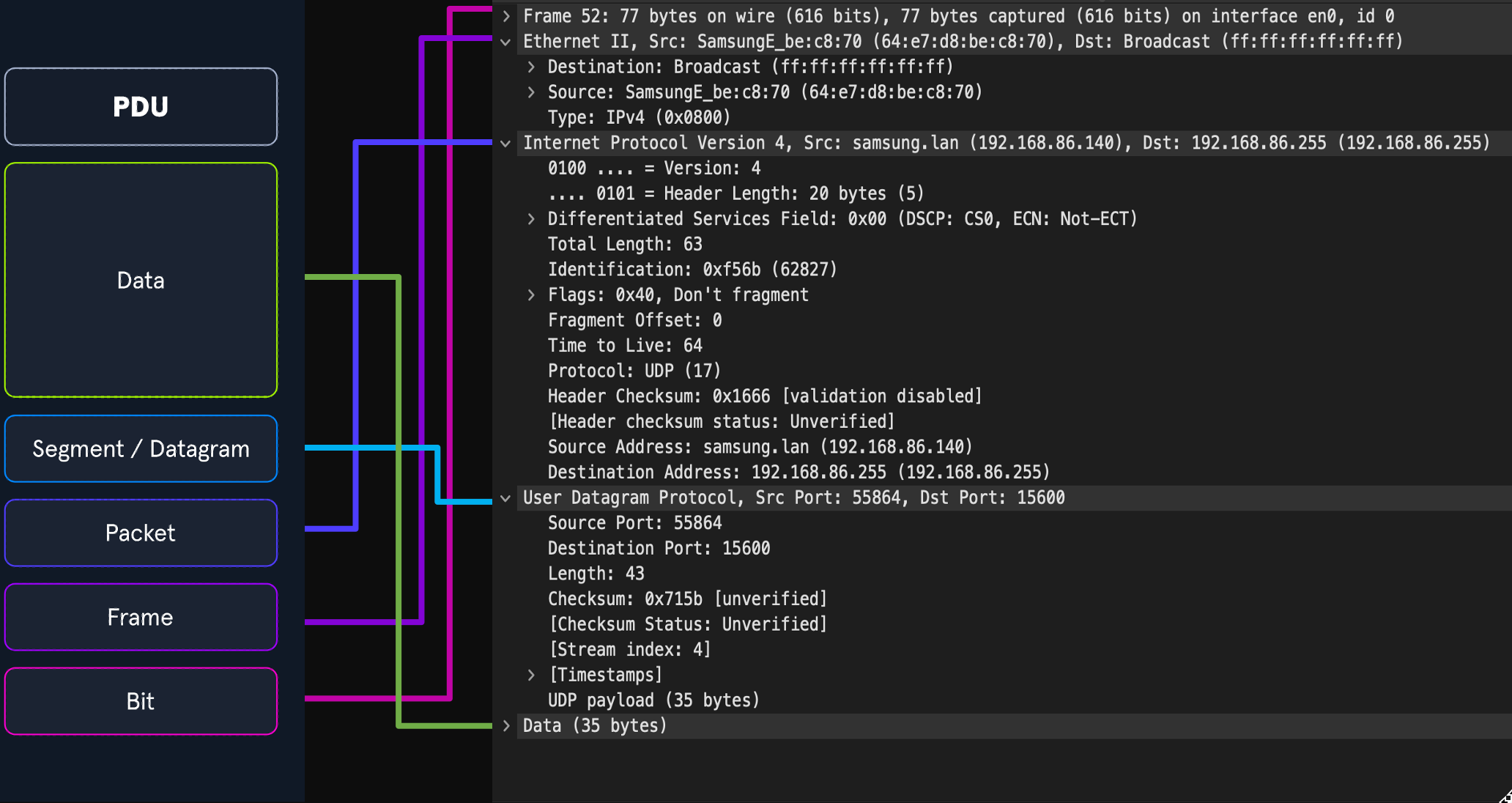
The image above shows us the makeup of a PDU side by side with a packet breakout from Wireshark's Packet Details pane. Please take note that when we see the breakout in Wireshark, it is in reverse order. Wireshark shows us the PDU in reverse because it is in the order that it was unencapsulated.
Addressing Mechanisms
Now that we have gone over the basic concepts driving networking behavior let us take some time to discuss the addressing mechanisms that enable the delivery of our packets to the correct hosts. We will begin with Media Access Control addresses first.
MAC-Addressing
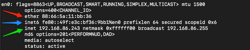
Each logical or physical interface attached to a host has a Media Access Control (MAC) address. This address is a 48-bit six octet address represented in hexadecimal format. If we look at the image below, we can see an example of one by the red arrow.
MAC-addressing is utilized in Layer two ( the data-link or link-layer depending on which model you look at ) communications between hosts. This works through host-to-host communication within a broadcast domain. If layer two traffic needs to cross a layer three interface, that PDU is sent to the layer three egress interface, and it is routed to the correct network. At layer two, this looks as though the PDU is addressed to the router interface, and the router will take the layer three address into account when determining where to send it next. Once it makes a choice, it strips the encapsulation at layer two and replaces it with new information that indicates the next physical address in the route.
IP Addressing
The Internet Protocol (IP) was developed to deliver data from one host to another across network boundaries. IP is responsible for routing packets, the encapsulation of data, and fragmentation and reassembly of datagrams when they reach the destination host. By nature, IP is a connectionless protocol that provides no assurances that data will reach its intended recipient. For the reliability and validation of data delivery, IP relies on upper-layer protocols such as TCP. Currently, there exist two main versions of IP. IPv4, which is the current dominant standard, and IPv6, which is intended to be the successor of IPv4.
IPv4
The most common addressing mechanism most are familiar with is the Internet Protocol address version 4 (IPv4). IPv4 addressing is the core method of routing packets across networks to hosts located outside our immediate vicinity. The image below shows us an example of an IPv4 address by the green arrow.
An IPv4 address is made up of a 32-bit four octet number represented in decimal format. In our example, we can see the address 192.168.86.243. Each octet of an IP address can be represented by a number ranging from 0 to 255. When examining a PDU, we will find IP addresses in layer three (Network) of the OSI model and layer two (internet) of the TCP-IP model. We will not deep dive into IPv4 here, but for the sake of this module, understand what these addresses are, what they do for us, and at which layer they are used.
IPv6
After a little over a decade of utilizing IPv4, it was determined that we had quickly exhausted the pool of usable IP addresses. With such large chunks sectioned off for special use or private addressing, the world had quickly used up the available space. To help solve this issue, two things were done. The first was implementing variable-length subnet masks (VLSM) and Classless Inter-Domain Routing (CIDR). This allowed us to redefine the useable IP addresses in the v4 format changing how addresses were assigned to users. The second was the creation and continued development of IPv6 as a successor to IPv4.
IPv6 provides us a much larger address space that can be utilized for any networked purpose. IPv6 is a 128-bit address 16 octets represented in Hexadecimal format. We can see an example of a shortened IPv6 address in the image below by the blue arrow.
IPv6 Address
Along with a much larger address space, IPv6 provides: Better support for Multicasting (sending traffic from one to many) Global addressing per device Security within the protocol in the form of IPSec Simplified Packet headers allow for easier processing and move from connection to connection without being re-assigned an address.
IPv6 uses four main types of addresses within its schema:
- Unicast - Addresses for a single interface.
- Anycast - Addresses for multiple interfaces, where only one of them receives the packet.
- Multicast - Addresses for multiple interfaces, where all of them receive the same packet.
- Broadcast - Does not exist and is realized with multicast addresses.
When thinking about each address type, it is helpful to remember that Unicast traffic is host to host, while Multicast is one to many, and Anycast is one to many in a group where only one will answer the packet. (think load balancing).
Even with its current state providing many advantages over IPv4, the adoption of IPv6 has been slow to catch on.
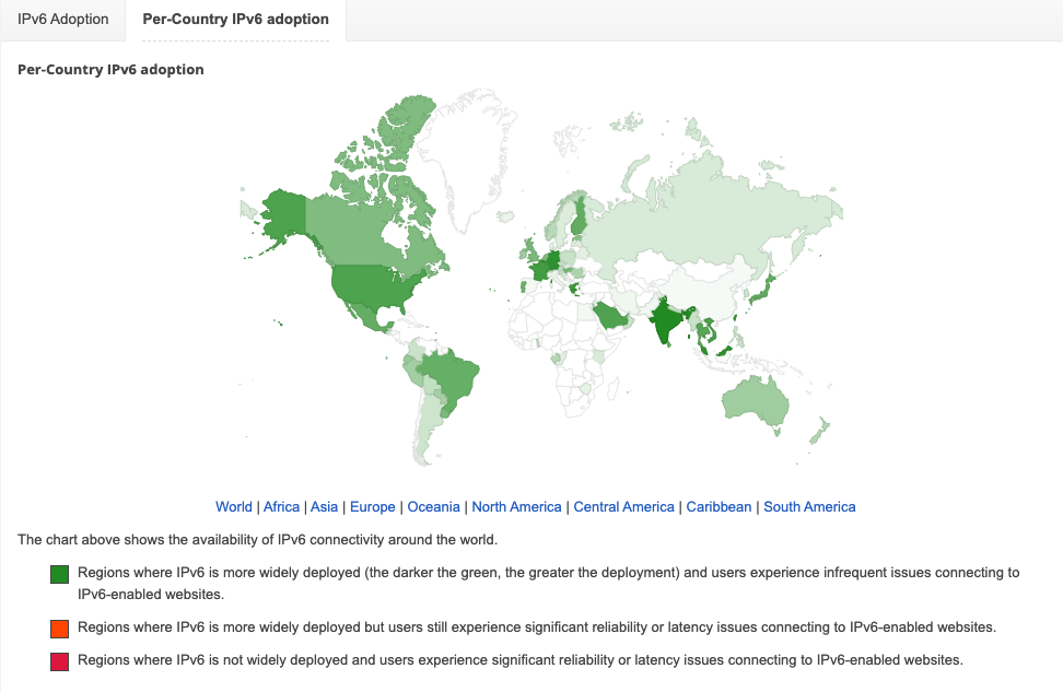
Adoption of IPv6
At the time of writing, according to statistics published by Google, the adoption rate is only around 40 percent globally.
TCP / UDP, Transport Mechanisms
The Transport Layer has several mechanisms to help ensure the seamless delivery of data from source to destination. Think about the Transport layer as a control hub. Application data from the higher layers have to traverse down the stack to the Transport layer. This layer directs how the traffic will be encapsulated and thrown to the lower layer protocols ( IP and MAC ). Once the data reaches its intended recipient, the Transport layer, working with the Network / Internet layer protocols, is responsible for reassembling the encapsulated data back in the correct order. The two mechanisms used to accomplish this task are the Transmission Control (TCP) and the User Datagram Protocol (UDP).
TCP vs. UDP
Let us take a second to examine these two protocols side by side.
- Transmission Connection-oriented - Connectionless. Fire and forget. Connection Establishment TCP uses a three-way handshake to ensure that a connection is established. UDP does not ensure the destination is listening.
- Data Delivery Stream-based conversations - packet by packet, the source does not care if the destination is active.
- Receipt of data Sequence and Acknowledgement - numbers are utilized to account for data. UDP does not care.
- Speed - TCP has more overhead and is slower because of its built-in functions. UDP is fast but unreliable.
By looking at the table above, we can see that TCP and UDP provide two very different data transmission methods. TCP is considered a more reliable protocol since it allows for error checking and data acknowledgment as a normal function. In contrast, UDP is a quick, fire, and forget protocol best utilized when we care about speed over quality and validation.
To put this into perspective, TCP is utilized when moving data that requires completeness over speed. For example, when we use Secure Shell (SSH) to connect from one host to another, a connection is opened that stays active while you issue commands and perform actions. This is a function of TCP, ensuring our conversation with the distant host is not interrupted. If it does get interrupted for some reason, TCP will not reassemble a partial fragment of a packet and send it to the application. We can avoid errors this way. What would happen if we issued a command like sudo passwd user to change the user's password on a remote host, and during the change, part of the message drops. If this were over UDP, we would have no way of knowing what happened to the rest of that message and potentially mess up the user's password or worse. TCP helps prevent this by acknowledging each packet received to ensure the destination host has acquired each packet before assembling the command and sending it to the application for action.
On the other hand, when we require quick responses or utilize applications that require speed over completeness, UDP is our answer. Take streaming a video, for example. The user will not notice a pixel or two dropped from a streaming video. We care more about watching the video without it constantly stopping to buffer the next piece. Another example of this would be DNS. When a host requests a record entry for inlanefreight.com, the host is looking for a quick response to continue the process it was performing. The worst thing that happens if a DNS request is dropped is that it is reissued. No harm, no foul. The user will not receive corrupted data because of this drop.
UDP traffic appears like regular traffic; it is a single packet, with no response or acknowledgment that it was sent or received, so there is not much to show here. However, we can take a look at TCP and how it establishes connections.
TCP Three-way Handshake
One of the ways TCP ensures the delivery of data from server to client is the utilization of sessions. These sessions are established through what is called a three-way handshake. To make this happen, TCP utilizes an option in the TCP header called flags. We will not deep dive into TCP flags now; know that the common flags we will see in a three-way handshake are Synchronization (SYN) and acknowledgment (ACK). When a host requests to have a conversation with a server over TCP
The client sends a packet with the SYN flag set to on along with other negotiable options in the TCP header.
- This is a synchronization packet. It will only be set in the first packet from host and server and enables establishing a session by allowing both ends to agree on a sequence number to start communicating with.
- This is crucial for the tracking of packets. Along with the sequence number sync, many other options are negotiated in this phase to include window size, maximum segment size, and selective acknowledgments.
The server will respond with a TCP packet that includes a SYN flag set for the sequence number negotiation and an ACK flag set to acknowledge the previous SYN packet sent by the host.
- The server will also include any changes to the TCP options it requires set in the options fields of the TCP header.
The client will respond with a TCP packet with an ACK flag set agreeing to the negotiation.
- This packet is the end of the three-way handshake and established the connection between client and server.
Let us take a quick look at this in action to be familiar with it when it appears in our packet output later on in the module.
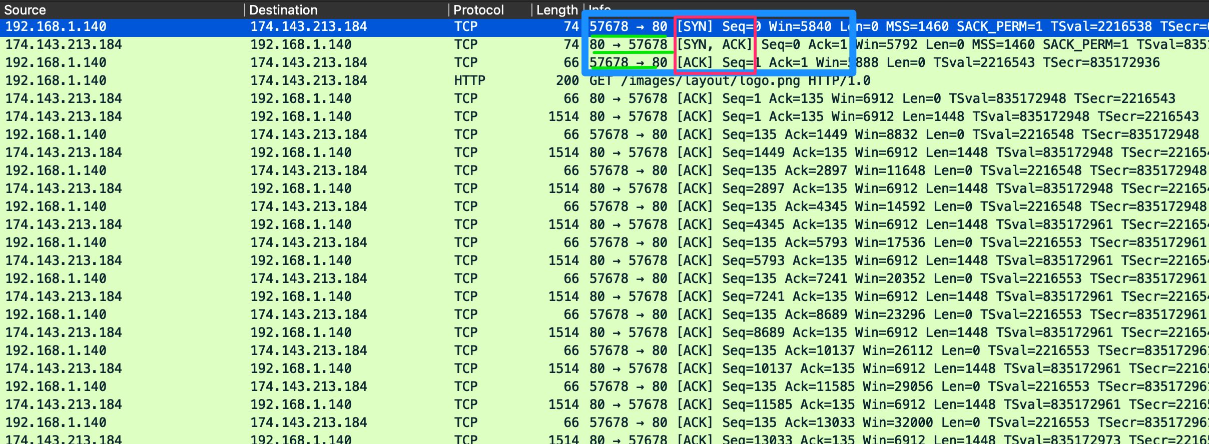
TCP Three-way Handshake
When examining this output, we can see the start of our handshake on line one. Looking at the information highlighted in the red box, we can see our initial Syn flag is set. If we look at the port numbers underlined in green, we can see two numbers, 57678 and 80. The first number is the random high port number in use by the client, and the second is the well-known port for HTTP used by the server to listen for incoming web request connections. In line 2, we can see the server's response to the client with an SYN / ACK packet sent to the same ports. On line 3, we can see the client acknowledge the server's synchronization packet to establish the connection.
Packet 4 shows us that the HTTP request was sent, and a session is established to stream the data for the image requested. We can see as the stream continues that TCP sends acknowledgments for each chunk of data sent. This is an example of typical TCP communication.
We have seen how a session is established with TCP; now, let us examine how a session is concluded.
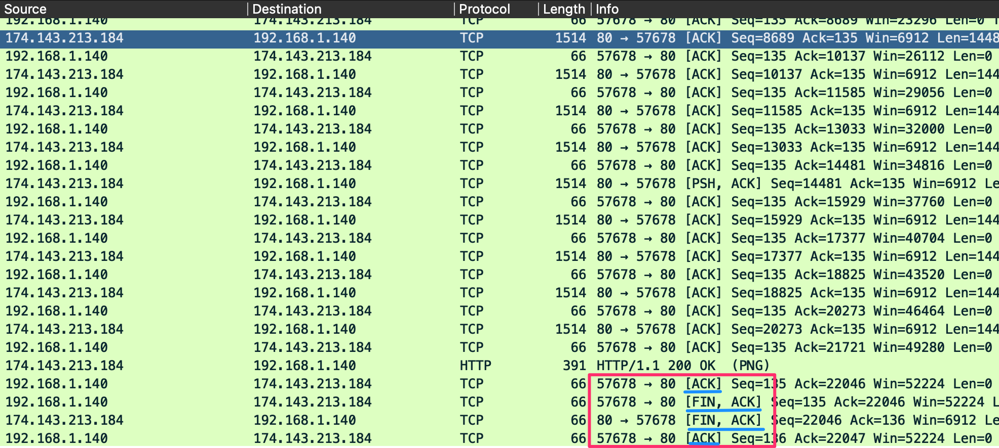
TCP Session Teardown
In the image above, a set of packets similar to our three-way handshake visible at the end of the output. This is how TCP gracefully shuts connections. Another flag we will see with TCP is the FIN flag. It is used for signaling that the data transfer is finished and the sender is requesting termination of the connection. The client acknowledges the receipt of the data and then sends a FIN and ACK to begin session termination. The server responds with an acknowledgment of the FIN and sends back its own FIN. Finally, the client acknowledges the session is complete and closes the connection. Before session termination, we should see a packet pattern of:
- FIN, ACK
- ACK
If we look at the image above detailing a session, we will see that this is the case. An output similar to this is considered an adequately terminated connection.
Questions
How many layers does the OSI model have?
How many layers are there in the TCP/IP model?
True or False: Routers operate at layer 2 of the OSI model?
What addressing mechanism is used at the Link Layer of the TCP/IP model?
At what layer of the OSI model is a PDU encapsulated into a packet? ( the number )
What addressing mechanism utilizes a 32-bit address?
What Transport layer protocol is connection oriented?
What Transport Layer protocol is considered unreliable?
TCP's three-way handshake consists of 3 packets: 1.Syn, 2.Syn & ACK, 3. _? What is the final packet of the handshake?